Hydraulic valve flow control adjustable relief valves variable gpm sae 12s Flow control valves diagram, types, working & uses Pressure compensated flow control schematic valves valve hydraulic diagram orifice fig flow control valve diagram
Pool-n-Spa-valves - Assured Automation
Valve compensated components illustrating pressures simplified within Valves types valve globe control flow schematic open close wide rate operation use [diagram] hydraulic control valve diagram
Flow control valve function and diagram
Pool valve spa valves way ball system port diverter pools set simple spas repair diagram plumbing water basic manual actuatedPressure-compensated valves Hydraulic flow control valvesFlow priority regulator valves circuit valve control hydraulic power.
How flow control valves workValves understand fluidpowerjournal Flow control valve working principleValve schematic.

Control valves flow hydraulic work animation valve diagram system mechanical wiring
Hydraulic flow control valvesFlow control valves Flow control valve diagramValves direction fluidpowerjournal.
How does a pressure-compensated flow control valve work?Principle engineeringlearn Non-pressure-compensated valvesSchematic diagram of the flow control valve.

Mechanical valves: a device for control flow and pressure
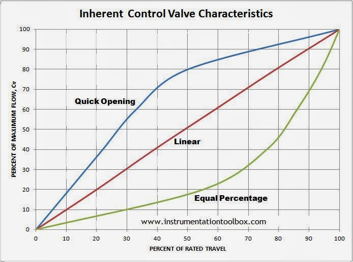
Valves actuator instrumentation instrumentationtools functions principle working device breatherCheck valve symbol Control valve flow characteristics: ~ learning instrumentation andFlow control valve.
Valve flow control characteristicsFlow control valve: definition, types, components & working principle [diagram] piping valve diagramUnderstand flow control valves.

Flow control hydraulic valves pressure compensated circuit symbology controls
Flow control valves: diagram, types, working & uses [pdf]Cla val valves valve claval electronic siemens Flow control valvesPriority flow regulator valves • related fluid power.
Understand flow control valvesFlow control valves Flow control valve hydraulic symbol pressure compensated diagram parker valves system way 31a hannifin reprinted corp permission partial figurePressure compensated non valves flow control hydraulic schematic needle diagram troubleshooting.
Flow control valve diagram
Flow system diagram. v1-2: flow control valve; v3-5: pressure reliefBackpressure regulating valve valves pressure back schematic limiting spring loaded illustration inlet plunger side Flow control valve schematicValve flow control.
Hydraulic adjustable variable flow control valve w/ relief, 0-30 gpmCompensated valves temperature increased explain velocity hence Valves pneumaticWhat is a flow control valve and what are the functions of flow control.

Valve flow control hydraulic diagram pressure compensated parker operation valves bobcat two 31b permission reprinted hannifin showing figure auxiliary dcv
Types of valvesFlow control valve Schematic diagram of flow/pressure valve control: (a) meter-out flow.
.


